Single User MIMO. It Didn’t Work, but the Lab Results Were Amazing
By Eric J. Black, CTO, Pivotal Commware
The world spectral efficiency record of 145.6 bps/Hz was set back in 2018 by an academic team at the University of Bristol using a Massive MIMO (mMIMO) testbed (128 radio chains)1. Since then, huge interest in commercial wireless systems using mMIMO technology has bloomed and it is a key part of 5G wireless standards2. However, in the real world, mMIMO has not realized even 10% of this demonstration’s potential3. At a recent industry 6G conference, a director from a major wireless carrier, while speaking on a panel to wireless OEMs, made the following statement: “Before you try to sell me the latest 6G technology, why don’t you go back and tell me why the ‘latest technology’ has not improved my spectral efficiency since 3G?” This fairly damning question highlights that the gap between industry and academic results clearly deserves some scrutiny. In the next few blog posts, I will attempt to pull apart some of the misconceptions about what mMIMO can and cannot do from a comparatively simple physics point of view.

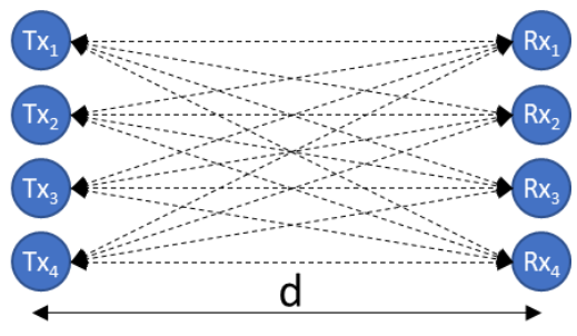
To start, let us study the limits of single user MIMO (SU-MIMO). Consider the situation depicted in Figure 1, with two SU-MIMO systems that are each made up of 4 idealized radiators (perfect, co-polarized, omnidirectional antennas with no mutual coupling effects on a half wavelength lattice, each element has its own DSP chain). The systems are oriented at broadside with respect to each other and are separated by a distance ‘d’ with a background environment of free space. Alternately, this setup can be considered as being inside a perfect anechoic chamber. The result is the same in that there are no available reflections or multipath present in the system.
This simple geometry allows us to calculate the coupling matrix between the Tx and Rx elements by accounting for the phase shift and 1/r2 propagation loss between elements (r being the distance between any Tx and Rx pair, dotted lines). I denote this matrix as ![]() and it is often referred to as the channel matrix in MIMO literature. Most of the practical challenges in MIMO implementation revolve around measuring the channel matrix and sharing those measurements between Tx and Rx in a timely manner. As such, the idealized model used here represents having perfect channel state information at both the transmitter and receiver and therefore is a best-case bound on MIMO performance.
and it is often referred to as the channel matrix in MIMO literature. Most of the practical challenges in MIMO implementation revolve around measuring the channel matrix and sharing those measurements between Tx and Rx in a timely manner. As such, the idealized model used here represents having perfect channel state information at both the transmitter and receiver and therefore is a best-case bound on MIMO performance.
Next, we need to invoke a little linear algebra. We can perform a singular value decomposition (SVD) of the channel matrix. SVD is a more generalized version of eigenvalue decomposition that can be used on arbitrary matrices. The SVD breaks the channel matrix into three new matrixes that contain the left eigenvectors (![]() ), eigenvalues (
), eigenvalues (![]() ) and right eigenvectors (
) and right eigenvectors (![]() ) respectively.
) respectively.

This is a hugely important representation. Recall that the eigenvectors of a matrix are orthogonal. If one encodes a wireless signal using an eigenvector, one can encode a second wireless signal using any of the other eigenvectors and the two signals will not interfere. Independently coding different wireless signals onto the eigenvectors places the signals on different spatial layers, allowing the frequency and time resources to be fully re-used. This is the core theoretical feature of MIMO systems that industry is trying to exploit.
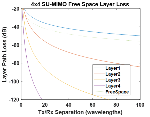
However, one crucial detail to pay attention to is the eigenvalues associated with the eigenvectors. The eigenvectors pass through the channel matrix unchanged except for a scaling factor, the eigenvalue. The physical interpretation of the eigenvalue is then straightforward. The magnitude of the eigenvalues is the loss of the spatial layer encoded by the corresponding eigenvector. It therefore becomes quite useful to examine what happens to the eigenvalues in our toy geometry (Figure 1) as the distance ‘d’ between transmitter and receiver increases. That result is plotted in Figure 2 as a function of the number of wavelengths separating the Tx and Rx arrays. Also plotted for reference is the generic 1/r2 propagation loss one would minimally expect for any wireless channel (dotted line).

As one would expect, the best MIMO layer (layer1) is 6dB better than free space, owing to 4 combined elements having 6dB better antenna gain than a single element. The remaining layers behavior as separation increases is striking. Inside of 8 wavelengths, all 4 layers have reasonable path loss for a wireless system to recover from. This allows a full 4x improvement in throughput. However, by a mere 100 wavelength separation, the second best spatial layer (Layer2) is over 30dB worse SNR than layer1! As a quick reality check, 100 wavelengths at 3.5GHz is less than 30 feet! This behavior arises due to the limited angular resolution of a finite antenna array. Without sufficient multipath, the benefits of SU-MIMO are sharply limited to being no better than a SISO link. This is not a function of number of elements. Going ‘Massive’ in this scenario scales the distance to the near-field/far-field boundary out by roughly the number of elements but does not yield any useful extra layers while in the far field.
In my next post, I will expand this model to study the case of perfect multipath by enclosing the system inside a shield room. This situation is more representative of the short range, indoor environments where most MIMO demos have taken place.
[1] W. Boukley Hasan, P. Harris, A. Doufexi and M. Beach, "Real-Time Maximum Spectral Efficiency for Massive MIMO and its Limits," in?IEEE Access, vol. 6, pp. 46122-46133, 2018, doi: 10.1109/ACCESS.2018.2866094.
[2] 3GPP Standards. Technical Specifications 38.913, 38.214, 38.211, 38.213
[3] Navarange, Nakul H. “Real-Life M-MIMO Case Studies - MASSIVE MIMO.” Coursera, Qualcomm, https://www.coursera.org/lecture/5g-training-qualcomm/real-life-m-mimo-case-studies-MQbVx.

