Single User MIMO. It Didn’t Work, but the Lab Results Were Amazing Part II
By Eric J. Black, CTO, Pivotal Commware
To read part I, click here
In my previous post, I showed how the benefit of Single User (SU) MIMO collapses in a free space environment. However, many academic reports showed capacity scaling merely as the number of antenna elements. One is correct to ask, how was that result achieved? My simple model showed that at distances inside the near-field/far-field boundary of the antenna systems, the eigenvalues of the channel matrix were quite good. Certainly, that was true for some of the very earliest results. However, more careful experiments made it clear that proximity alone was not providing the additional MIMO layers.
Nearly all testing of MIMO systems was (and is) done indoors, frequently inside of RF shielded rooms and laboratories. Such environments are very interesting, as they create nearly the perfect conditions for SU-MIMO to perform optimally. We can study the impact of this with the simple model from my previous post with a few tweaks. The original model is shown pictorially in Figure 1 (left side). In this model, a 4-element, co-polarized MIMO transmit array is communicating with a 4-element co-polarized receive array separated in free space by a distance ‘d’. The channel matrix C1 is made up of the 16 coefficients describing the interconnection of the 4 Tx elements to the 4 Rx elements (Figure 1, right side).

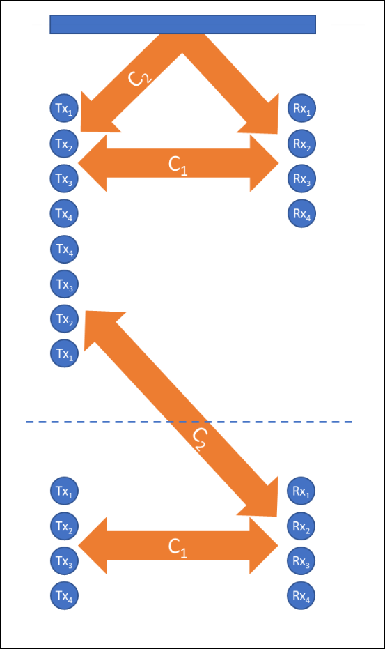
There are several ways to extend the model to handle a reflected path. I chose to use the classic ‘method of images’, where a mirror image of the Tx sources is used to remove the reflection plane. I illustrate this in Figure 2. Note that this process creates 16 new paths between the mirror image Tx and original Rx elements. As before, those paths can be condensed into a new channel matrix C2. Furthermore, C1 and C2 superposition to give rise to the joint channel matrix which describes the full behavior of the propagation environment.

As before, we can calculate the singular value decomposition of this joint channel matrix (C1+C2) and the effect on the quality of the layer2 eigenvalue is remarkable (Figure 3). Layer1 and Layer2 have nearly the same interference free path loss out to well over 400 wavelengths. This is quite an improvement over the original case where -60dB path loss point for Layer2 was less than 25 wavelengths!
There is a bunch of interesting physics going on here. The Layer1 and 2 path losses start to oscillate around each other as separation increases past 200 wavelengths. Eventually Layer2 dies out at very large separations (not shown, close to 1000 wavelengths) unless the perfect infinite mirror plane is also moved farther away from the arrays. The drop off is due to the separation of the Tx and Rx arrays being so large that the reflected sources are not resolvable in the angular sense. In terms of this model, C1 and C2 look very similar if the distance to the mirror is very small compared to Tx/Rx separation. Moving the mirror plane farther away fixes this.
There is also an interesting ‘quiet spot’ at about 180 wavelength separation. Bonus points for students who can figure out what is going on there.
It is not difficult to add the other 5 walls of a closed metal box that most shielded rooms are constructed as. Each mirror doubles the number of channel matrixes making up the joint channel matrix (64 in case anyone is counting). Throw in dual polarization and a comparatively short range (most shieldrooms are not hundreds of feet long). Very quickly, you can see how the early academic experiments reached spectacularly high spectral efficiencies!
Obviously, the real world is somewhere in between the two extremes I have shown in these two posts. Unfortunately, it does appear that real world scattering environments are more like the free-space case (read: rich scattering environments are a myth outdoors), as SU-MIMO gained little commercial traction. That said, industry pivoted away from SU-MIMO toward more interesting, but challenging, MIMO techniques such as Multi-User MIMO (MU-MIMO) and its successor Cell-Free Massive MIMO.
In my next post, I will survey some of the latest ideas for improving MIMO performance including MU-MIMO, Cell-Free MIMO, RIS and Repeaters.

