Single User MIMO. It Didn’t Work, but the Lab Results Were Amazing Part III
By Eric J. Black, CTO, Pivotal Commware
To read part II, click here
In my first post in this three-part series, I used a simple channel matrix formulation to show that free space does not support any extra modes between two Single-User MIMO (SU-MIMO) systems in the far field. Throughput only scaled logarithmically with signal to noise ratio. In a subsequent post, I went on to show that placing that same system inside a closed metal box would yield a plurality of modes that gave the classic academic result where throughput scales linearly with the radio chains in the system. Unfortunately, the real world appears to be more like the free space case, with throughput of SU-MIMO systems only rarely achieving more than a factor of 2 or 3 of increase in throughput over dual-polarized links for a 20-30x cost increase.
This is a bit of a problem for a wireless operator. Revenue per user in general has been falling for over a decade. Spending 20-30x for 2-3x improvement is not a viable strategy. So, the industry has been working on more advanced MIMO techniques to maximize the value of such complex radio systems. SU-MIMO’s downfall was its sharp dependence on the quality of the multipath/scattering environment it was used in. Two more modern MIMO techniques I will discuss here avoid that dependency (mostly).
Perhaps the most modern MIMO approach is a technique called Multi-User MIMO (MU-MIMO). In MU-MIMO, the antennas on one side of the link are widely dispersed. This configuration looks topologically like cellular systems today, a single base station with many antenna elements that serves multiple users, each having much smaller numbers of antennas than the base station. There are two key distinctions relative to SU-MIMO.
The first distinction is the added technical challenge of sharing crucial channel state information (CSI) between multiple devices. The UEs fundamentally do not talk to each other directly in the 3GPP implementation. Indeed, perhaps the largest technical challenge for MU-MIMO is how best to make use of limited CSI but still perform well in real deployments. The path loss model we have been using assumes perfect CSI so any results from it are a bit of a cheat in that they represent idealized MU-MIMO performance.
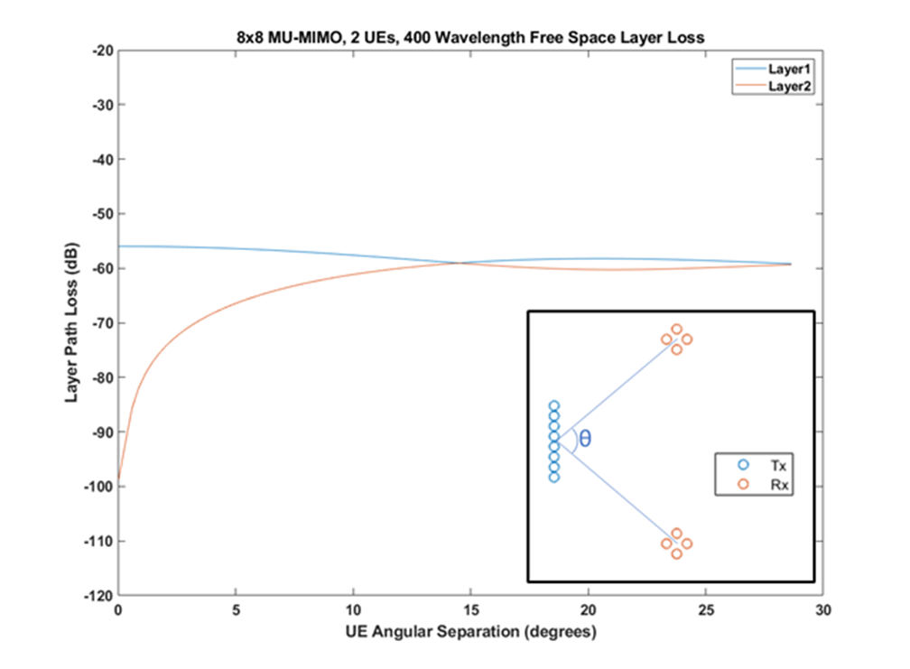
The second distinction is that the UEs, and thus their antennas, can be well separated from one another, avoiding the angular resolution issue that troubled our free-space SU-MIMO system. Shown in Figure 1, the base station must separate the UEs on both transmit and receive. The limit where this breaks down depends on the base station antenna beamwidth. In the calculation an 8-element linear array with a beamwidth of 13 degrees serves two UEs with 4 antennas each. It is not an accident that 13 degrees is also the angle where we see the layer 2 path loss diverge from layer 1 as we vary the angular separation between the UEs in our simple model. Evidently, the two UEs can get too close to each other in the angular sense for MU-MIMO to offer much benefit. However, it is reasonable to assume that there will be many situations where users are well separated and allow MU-MIMO benefit.

One interesting scenario for MU-MIMO is that of Fixed Wireless Access (FWA). In suburban settings, the customer access point separation is almost enforced by the normal suburb layout. In denser urban deployments like to an MDU, MU-MIMO is unlikely to offer much benefit unless the gNB is quite close to the MDU in question.
Another MIMO approach that has recently appeared in academic literature is called Cell-Free-Massive-MIMO (CFM-MIMO). In CFM-MIMO, the base station antennas are no longer co-located. At first glance, the hardware looks like a densified cellular network using femto or pico-cells. However, there is quite a bit more going on under the hood. The dispersed base station nodes are coordinated jointly to form a coherent, MIMO antenna system with a similar channel matrix formalism as the original SU-MIMO setup. The latency requirements, CSI challenges, and other practical engineering challenges are significant. However, the geometry of CFM-MIMO has the nice property of removing the angular resolution problem regardless of the propagation environment. Antenna engineers will recognize that UEs in CFM-MIMO are deep in the near-field of the base station joint-antenna pretty much always. This means that angular resolution of the system is not even defined in a meaningful way.
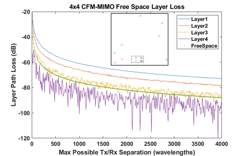
The possible positions of the Tx and Rx antennas in CFM-MIMO are nearly infinite. However, with rare exceptions, the throughput of CFM-MIMO is surprisingly stable. Figure 2 shows one such configuration (inset) as the configuration is scaled with average Tx/Rx separation. The layer losses generally track the expected divergence loss of free space out to any scale. Therefore, the number of supportable layers depends only on the size of the region covered by the CFM-MIMO system, with small regions supporting the highest layer count.

The challenges to cost effective implementation of both MU and CFM MIMO are daunting but have been the subject of intense research both in industry and academia. However, it is worth remembering that both approaches have negligible impact on individual user throughput. Instead, the throughput gains manifest at the network level, meaning lower operator OPEX. This is quite unfortunate, as one of the hottest applications of 5G wireless has been that of FWA where single-user throughput requirements are intense. It remains a bit of an open question if CFM-MIMO can be cost-effective with such a high node count and the added low latency infrastructure.
In this series we showed how the environment MIMO systems are deployed in can dominate MIMO performance far more than the hardware actually does. This is problematic as MIMO is being deployed in many locations around the world. At IWPC’s webinar on Wednesday, February 8, 2023, I will be proposing a solution to the low-quality scattering that fundamentally limits MIMO performance. The technique makes use of repeaters to intentionally engineer the scattering environment to make maximum use of MIMO systems potential while not imposing any new latency or computational requirements to the operator. I look forward to seeing you there: Pivotal CTO Eric Black to Speak at IWPC Webinar.

